#1
Jan 25, 2012, 5:44 pm
Hide
Some of this information has been helpful toward my winter rebuild of the MGB, so I though some of you could benefit from the basic engineering principals outlined here. Old school technology, yes, but sometimes it helps to go back to where we started from in order to perfect our efforts to supress side tremmy to the trunion bearings and eliminate this all to common failure in our cars.
http://www.youtube.com/watch?v=rLDgQg6bq7o
#2
Jan 26, 2012, 2:07 am
Hide
I think the biggest take away from this is how they achieved the main winding was of the normal lotus-o-delta type placed in panendermic semi-boloid slots in the stator, every seventh conductor being connected by a nonreversible trem'e pipe to the differential girdlespring on the up-end of the grammeters.
That was and still is some very heavy stuff!
#3
Jan 26, 2012, 11:35 am
Hide
ZUL8TR wrote

I think the biggest take away from this is how they achieved the main winding was of the normal lotus-o-delta type placed in panendermic semi-boloid slots in the stator, every seventh conductor being connected by a nonreversible trem'e pipe to the differential girdlespring on the up-end of the grammeters.
That was and still is some very heavy stuff!
I just realized how strikingly similar this product is to a TurboZUL8TR.
#4
Jan 27, 2012, 4:01 am
Hide
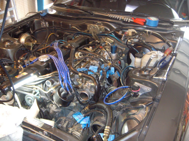
Its true. You can easily spot the treme pipe in this pic!
#5
Jan 27, 2012, 4:29 am
Hide
All I spotted was the painter tape

#6
Jan 27, 2012, 8:42 am
Hide
Oh, its just around behind the side in front of the dingle arm. That should make it obvious now.
#7
Jan 27, 2012, 10:42 am
Hide
ZUL8TR wrote
Oh, its just around behind the side in front of the dingle arm. That should make it obvious now.
Completely obvious now, thanks. What if you incorporated a base-plate of prefabulated amulite, surmounted by a malleable logarithmic casing in such a way that the two spurving bearings were in a direct line with the pentametric fan. The main winding was of the normal lotus-o-delta type placed in panendermic semi-boloid slots in the stator, every seventh conductor being connected by a nonreversible trem'e pipe to the differential girdlespring on the 'up' end of the grammeters.
Forty-one manestically spaced grouting brushes were arranged to feed into the rotor slipstream a mixture of high S-value phenylhydrobenzamine and 5% reminative tetryliodohexamine. Both of these liquids have specific pericosities given by P = 2.5C.n^6-7 where n is the diathetical evolute of retrograde temperature phase disposition and C is Cholmondeley's annular grillage coefficient. Initially, n was measured with the aid of a metapolar refractive pilfrometer, but up to the present date nothing has been found to equal the transcendental hopper dadoscope. This has been successfully used for operating nofer trunnions. In addition, whenever a barescent skor motion is required, it may be employed in conjunction with a drawn reciprocating dingle arm to reduce sinusoidal depleneration.
This worked on my MG, BTW, and that car is British.
#8
Jan 27, 2012, 11:28 am
Hide
Of course it would work well for a British vehicle because whenever fluorescent square motion is required, it may also be employed in conjunction with the drawn reciprocation dingle arm, to reduce sinusoidal depleneration.
But you need to remember the Z is Japanese, thus a barescent skor motion is required, it may be employed in conjunction with a drawn non-reciprocating dingle arm to increase sinusoidal depleneration.
There lies the difference between British and Japanese engineering. Let's not even get started on the French and Italian stuff and how they dealt with modial interaction of magneto-reluctance and capacitive directance.
#9
Jan 27, 2012, 12:08 pm
Hide
ZUL8TR wrote
Of course it would work well for a British vehicle because whenever fluorescent square motion is required, it may also be employed in conjunction with the drawn reciprocation dingle arm, to reduce sinusoidal depleneration.
But you need to remember the Z is Japanese, thus a barescent skor motion is required, it may be employed in conjunction with a drawn non-reciprocating dingle arm to increase sinusoidal depleneration.
There lies the difference between British and Japanese engineering. Let's not even get started on the French and Italian stuff and how they dealt with modial interaction of magneto-reluctance and capacitive directance.
I don't know Mark. I mean I see your point. but is seems like an overly simplistic, risky approach void of standard redundencies prevelent in sound horizontal based pressure applications. I'd sure like to hear another opinion before I'd try that on my car. Anyone? Dan??